Home ⇒ Overview Courses ⇒ Electropneumatics
Introduction electropneumatics
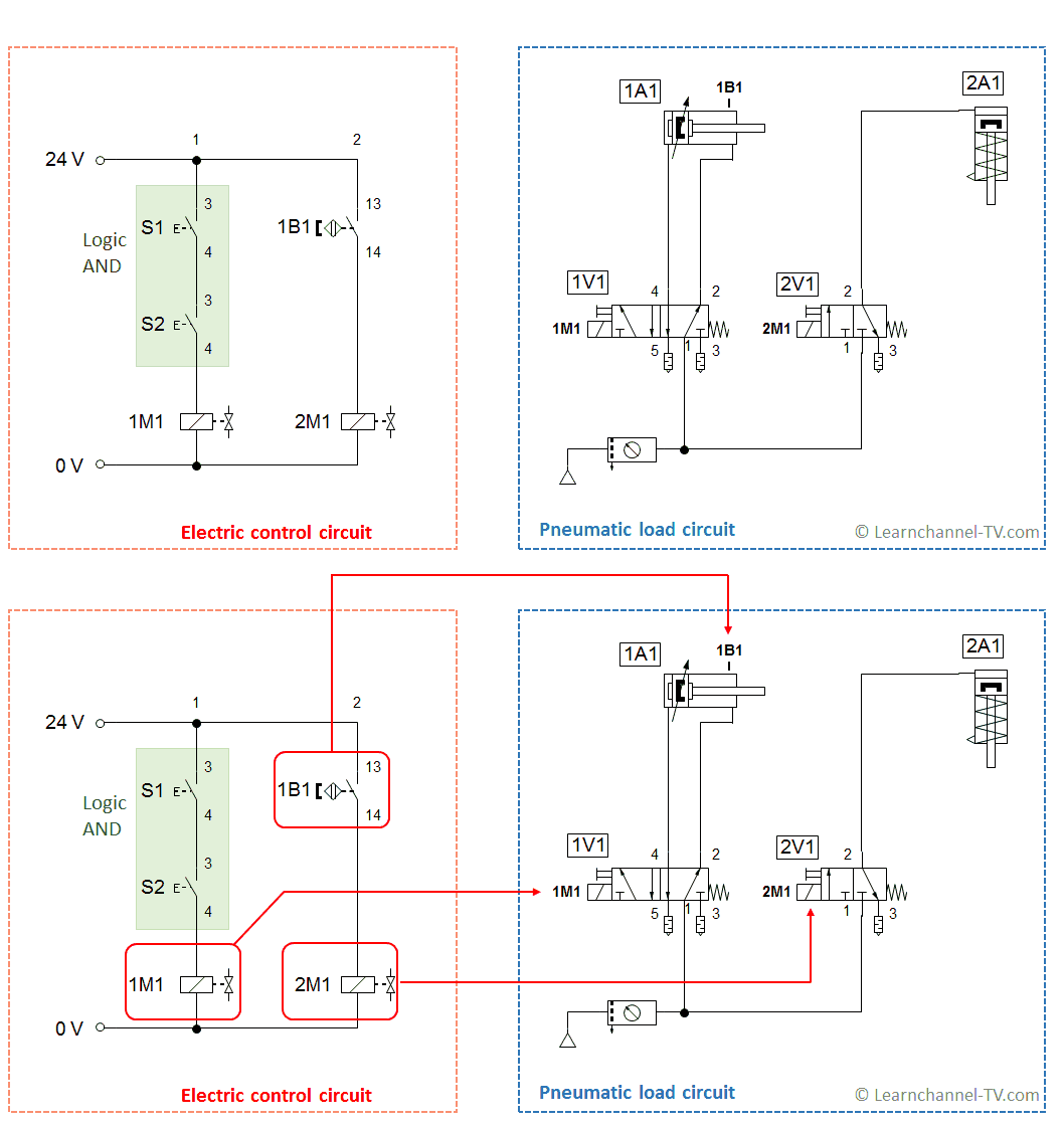
In electropneumatics distinction is made between the electric circuit and the pneumatic load circuit.
In the electropneumatics the input signals are processed within the electrical control circuit. The input elements are usually electrical contacts (buttons, switches) and electronic sensors. The control voltage is typically 24V DC1.
In the pneumatic circuit, valves are electrically-operated, which act as control elements for the actuators (cylinders, motors, etc). Logical functions are not implemented here. The following figure illustrates the functioning:

Electro pneumatic circuit - how to read
An electrically-actuated valve switches mechanically the compressed air; on the other hand the belonging valve solenoid is found itself on the electrical side. The figure above illustrates this.
1V1: Both sides operated directional valve, also referred to as pulse or bistable directional control valve. This directional control valve has a memory function.
2V1: spring return-way valve, that is, jumps after pressing once again in the initial position.
1 DC Δ Direct current
Watch our video about Pneumatics and Electropneumatics:
From the content:
0:00 Introduction Pneumatics
2:00 What is pressure?
3:09 Combined Gas Law, calculate a compressor
3:57 FRL Unit (Filter, Regulator, Lubricator)
6:49 Pneumatic circuit with indirect-operated DCV
7:33 Two-Pressure valve (Logic And valve)
8:18 Shuttle valve (Logic Or valve)
8:57 Indirect controlled systems
10:32 Pneumatic history part 1 12:26 Structure of a pneumatic circuit
12:34 Pneumatic history part 2
14:55 What is electropneumatics
17:29 Preview
On our own behalf: Thanks to the company Cofaso for the support of our technicians:


