
Measuring bridge with strain gauges
Strain gauges were invented by Arthur Claude Ruge in 1938 in Massachusetts, USA. He recognized the linear relationship between the linear expansion of a conductor and its electrical resistance, and how this could be used to measure bending and compression.
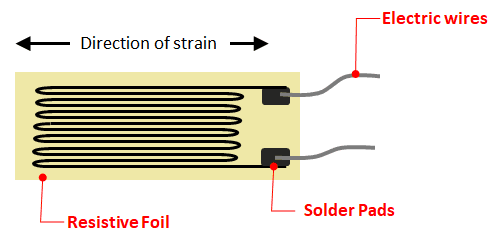
The construction of an electrical strain gauge is simple: a wafer-thin conductor is placed on a carrier foil. Constantan is often used for the conductors because of its high temperature stability.
Strain gauge - function
A fundamental parameter of the strain gage is the so-called gage factor (GF), which describes its sensitivity to strain. The GF is defined as the ratio of the fractional change in electrical resistance ΔR / R to the fractional change in length, or strain ε:
GF = ΔR / R | ε = ΔL / L
. ΔL / L
=> GF = ΔR / R or ΔR = GF * ε * R
. ε
Example: The expansion of ε = 0.2% of a strain gauge with a GF of 2 results in an increase in resistance of 0.4%.
Quarter-, Half-, Full-bridge
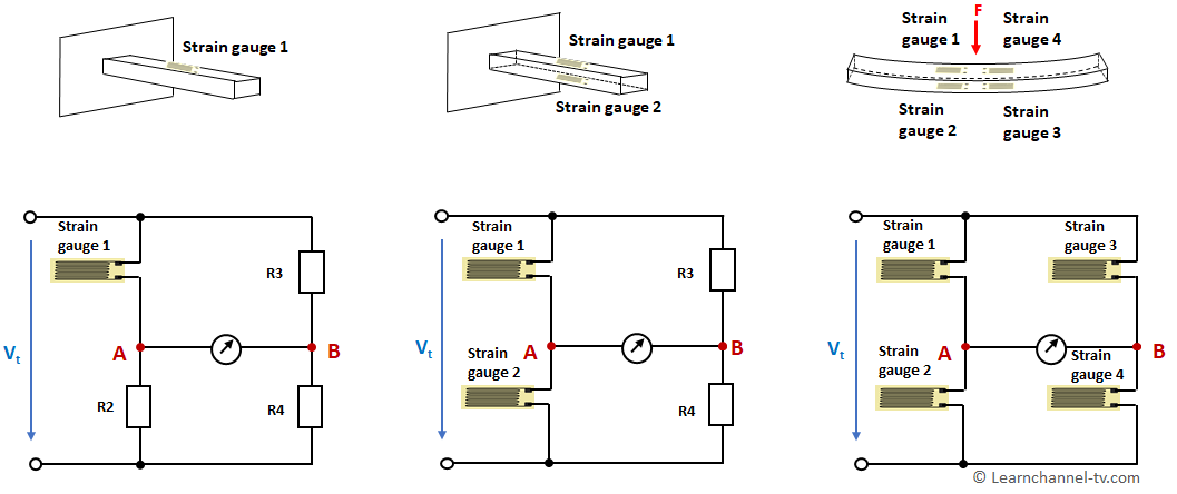
Usually 1 or 2 or 4 strain gauges are installed in a Wheatstone bridge. The names quarter, half and full bridge result from this. The nominal resistance R0 of all strain gauges are usually the same. Typical values in the unloaded state are R0 = 120, 350, 700 or 1000 Ω.
The full bridge has the highest sensitivity (4 times the sensitivity compared to the quarter bridge). Since disturbances such as temperature drift have the same effect on all four strain gauges, this results in an effective compensation of these disturbance variables. When installing the strain gauges, make sure that two are stretched and two are compressed.
Wheatstone bridge strain gage circuit – Quarter-, Half-, Full-bridge
Work Order: Full bridge with strain gages
- The strain gages used in a full bridge have a resistance R0 of 700 Ω, a maximum strain ε of 4 mm/m and a gage-factor of 2.1. What is the maximum resistance change ΔR of the strain gages?
Calculate the maximum bridge voltage VBR for this case. The supply voltage V of this measuring bridge is 10 V.
